Testing communication relays with a multimeter is a crucial skill for anyone working with electrical or communication systems. Relays are devices that use an electrical signal to open or close a switch, allowing for the control of high-power circuits with low-power signals. In communication systems, relays are essential for routing signals, isolating circuits, and ensuring proper functioning. Whether you’re troubleshooting a malfunctioning system or verifying the integrity of a new relay, knowing how to test a communication relay with a multimeter will save you time and effort.
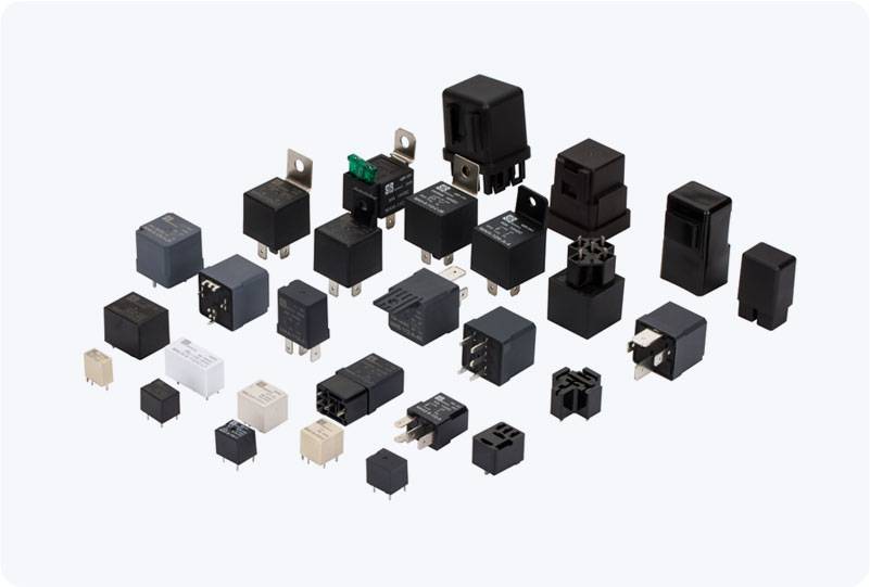
In this article, we’ll go over a step-by-step guide on how to test communication relays using a multimeter. We’ll cover what tools you need, what to look for, and how to properly check the relay’s functionality to ensure it’s working as intended. 1. Understanding the Relay Structure Before we begin testing, it’s important to understand the basic structure of a communication relay. A typical relay consists of two main components: the coil (or electromagnet) and the switch contacts (commonly known as NO (Normally Open) and NC (Normally Closed)). Coil: This is where the control voltage is applied. When voltage is applied to the coil, it generates a magnetic field that causes the switch contacts to change their state.
Leave a Reply
You must be logged in to post a comment.