Testing a communication relay with a multimeter is a crucial skill for anyone involved in electronics, especially in fields like telecommunications, automation, and electrical troubleshooting. Relays play a significant role in controlling circuits by using an electromagnetic coil to open or close contacts. They are often found in communication systems to manage signal routing, power switching, and fault detection. Understanding how to test a relay ensures that your system functions correctly and reliably. In this article, we’ll go through the necessary steps to test a communication relay using a multimeter.
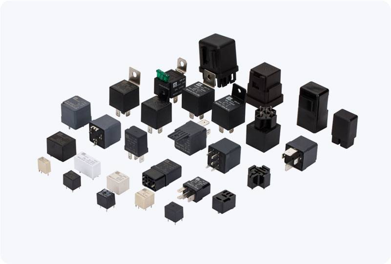
1. Understanding the Relay Components Before diving into the testing process, it’s important to understand the basic structure of a communication relay. A typical relay consists of: Coil Pins: These are the pins connected to the electromagnetic coil. Applying power to the coil activates the relay and changes the state of the switch. Switch Pins: The relay has multiple switch pins, usually including: Common (COM): The central pin that connects the relay to the circuit. Normally Open (NO): This pin remains open when the relay is de-energized and closes when the relay is energized.